

-
Products
Overview Products

-
2D Cutting
-
Tube Cutting
-
3D Cutting
-
Intelligent Welding
-
Intelligent Cutting Head
-
Industrial Automation
-
Industrial Software
-
Combination
-
Combination
BOCHU New Product -
Combination
BOCHU New Product -
Controller
BOCHU New Product -
2D Cutting Head
Tube Cutting Head
3D Cutting Head
Consumables
BOCHU New Product -
Servo
BOCHU New Product -
Industrial 4.0
-
- Support
- About
- Online Store


- Software Download
- Manual
- Video
- Tutorial
Ⅰ. Introduction
Simulate is adopted in the final checking stage after all parts have been processed and nested. Generally there are dynamic simulation and static simulation.

Ⅱ. Usages
| Simulation | Dynamic | Static |
| Scenario |
Check the actual cutting head status, and cutting order, eg., swing angle, the interferences between the cutting head and the parts.
|
Quickly view the actual cutting order, by watching toolpath processing sequence.
|
| How to use |
Select parts or toolpath, and click Simulate to start directly. Click the forward or backward button to adjust the speed. |
No need to select part or toolpath. Click the empty area, and click the forward or backward button. |
| Notices |
The cutting head model must be configured correctly. Please refer to TubesT - Cutting Head Setup Guide for details. |
The part or toolpath cannot be selected during simulation. If clicking forward or backward after selecting the toolpath, the order of the toolpath will be adjusted accordingly. |


Ⅲ. FAQs
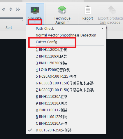
1. Why is there no cutting head after I clicked Simulate?
The reason might be that the cutting head model is not configured or not related. Please refer to TubesT - Cutting Head Setup Guide for details.
2. Why is the corresponding 3D model not displayed during simulation?
(1) Rendering Mode is not enabled.

(2) The configured cutting head model has not been related to the 3D model file.

3. How to check the bevel angle during simulation?
The angle of A-axis will be displayed in real-time during simulation in the bottom right corner. To check the angle of B-axis, please contact our technical support.

4. How to handle the prompt "Currently using a 2D Laser Head (CHC) to simulate the bevel toolpath. Unable to determine if there is a collision…” during bevel part simulation?
This is because the cutting head in your software is 2D, which cannot detect the bevel toolpath. Please refer to TubesT - Normal Vector Error Detection to detect vector error, or observe whether there is interference during simulation.
If you are using BLT Intelligent Cutting Head, you can contact BOCHU technical support for 3D model.
You may refer to TubesT - Collision-Avoid to know about the differences between 2D cutting head and 3D cutting head

Ⅰ. Introduction
Simulate is adopted in the final checking stage after all parts have been processed and nested. Generally there are dynamic simulation and static simulation.
Ⅱ. Usages
| Simulation | Dynamic | Static |
| Scenario |
Check the actual cutting head status, and cutting order, eg., swing angle, the interferences between the cutting head and the parts.
|
Quickly view the actual cutting order, by watching toolpath processing sequence.
|
| How to use |
Select parts or toolpath, and click Simulate to start directly. Click the forward or backward button to adjust the speed. |
No need to select part or toolpath. Click the empty area, and click the forward or backward button. |
| Notices |
The cutting head model must be configured correctly. Please refer to TubesT - Cutting Head Setup Guide for details. |
The part or toolpath cannot be selected during simulation. If clicking forward or backward after selecting the toolpath, the order of the toolpath will be adjusted accordingly. |
Ⅲ. FAQs
1. Why is there no cutting head after I clicked Simulate?
The reason might be that the cutting head model is not configured or not related. Please refer to TubesT - Cutting Head Setup Guide for details.
2. Why is the corresponding 3D model not displayed during simulation?
(1) Rendering Mode is not enabled.
(2) The configured cutting head model has not been related to the 3D model file.
3. How to check the bevel angle during simulation?
The angle of A-axis will be displayed in real-time during simulation in the bottom right corner. To check the angle of B-axis, please contact our technical support.
4. How to handle the prompt "Currently using a 2D Laser Head (CHC) to simulate the bevel toolpath. Unable to determine if there is a collision…” during bevel part simulation?
This is because the cutting head in your software is 2D, which cannot detect the bevel toolpath. Please refer to TubesT - Normal Vector Error Detection to detect vector error, or observe whether there is interference during simulation.
If you are using BLT Intelligent Cutting Head, you can contact BOCHU technical support for 3D model.
You may refer to TubesT - Collision-Avoid to know about the differences between 2D cutting head and 3D cutting head

